
Page 24 - DuraJet™ / AlumaJet™ Arches
P. 24
DURAJET™ ARCH
Installation
Utility Connections
Air
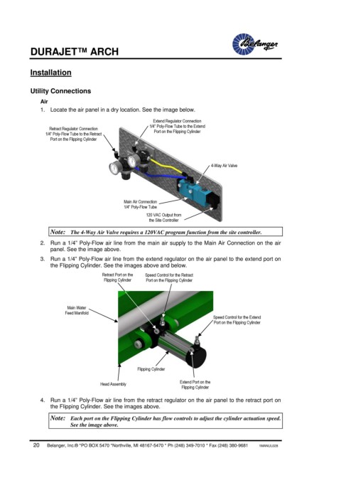
1. Locate the air panel in a dry location. See the image below.
Extend Regulator Connection
1/4” Poly-Flow Tube to the Extend
Retract Regulator Connection
1/4” Poly-Flow Tube to the Retract Port on the Flipping Cylinder
Port on the Flipping Cylinder
4-Way Air Valve
Main Air Connection
1/4” Poly-Flow Tube
120 VAC Output from
the Site Controller
Note: The 4-Way Air Valve requires a 120VAC program function from the site controller.
2. Run a 1/4” Poly-Flow air line from the main air supply to the Main Air Connection on the air
panel. See the image above.
3. Run a 1/4” Poly-Flow air line from the extend regulator on the air panel to the extend port on
the Flipping Cylinder. See the images above and below.
Retract Port on the Speed Control for the Retract
Flipping Cylinder Port on the Flipping Cylinder
Main Water
Feed Manifold
Speed Control for the Extend
Port on the Flipping Cylinder
Flipping Cylinder
Extend Port on the
Head Assembly
Flipping Cylinder
4. Run a 1/4” Poly-Flow air line from the retract regulator on the air panel to the retract port on
the Flipping Cylinder. See the images above.
Note: Each port on the Flipping Cylinder has flow controls to adjust the cylinder actuation speed.
See the image above.
20 Belanger, Inc.® *PO BOX 5470 *Northville, MI 48167-5470 * Ph (248) 349-7010 * Fax (248) 380-9681 1MANUL028