
Page 28 - AirBlade® Dryer Signature® Series
P. 28
AIRBLADE® DRYER Signature ® Series
Installation
AirBlade® Select, Frame Assembly
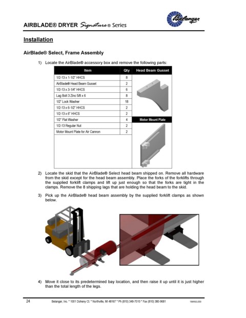
1) Locate the AirBlade® accessory box and remove the following parts:
Item Qty Head Beam Gusset
1/2-13 x 1-1/2” HHCS 8
AirBlade® Head Beam Gusset 2
1/2-13 x 3-1/4” HHCS 6
Lag Bolt 3 Zinc 5/8 x 6 8
1/2” Lock Washer 18
1/2-13 x 6-1/2” HHCS 2
1/2-13 x 6” HHCS 2
1/2” Flat Washer 4 Motor Mount Plate
1/2-13 Regular Nut 2
Motor Mount Plate for Air Cannon 2
2) Locate the skid that the AirBlade® Select head beam shipped on. Remove all hardware
from the skid except for the head beam assembly. Place the forks of the forklifts through
the supplied forklift clamps and lift up just enough so that the forks are tight in the
clamps. Remove the 8 shipping lags that are holding the head beam to the skid.
3) Pick up the AirBlade® head beam assembly by the supplied forklift clamps as shown
below.
4) Move it close to its predetermined bay location, and then raise it up until it is just higher
than the total length of the legs.
24 Belanger, Inc. * 1001 Doheny Ct. * Northville, MI 48167 * Ph (810) 349-7010 * Fax (810) 380-9681 1MANUL009