
Page 1641 - Foton Workshop Manual - Auman EST-M
P. 1641
Electrical system –circuit EL - 217
System description: IN
The battery current flows from the fuse F\L1 in the vehicle frame fuse box through the fuse F22 in the
instrument panel fuse box to the pins 30 and 85 of the small lamp relay R08. when the illumination DI
combination switch is put into small lamp position, the small lamp switch is earthed and the small lamp relay
R08 coil is powered up and magnetic field is generated. The contacts of the small lamp relay R08 are closed.
EG
The current is ouput from the pin 87 of the small lamp relay R08 to related illumination terminals of the
switches or control modules and are earthed at the other terminals of the switches or control modules, so that
the background lamps are on. TR
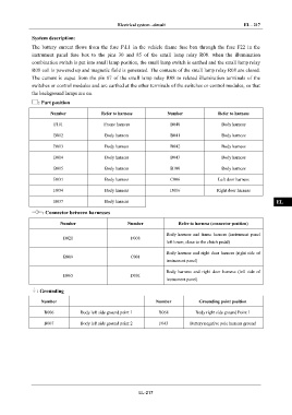
: Part position
AX
Number Refer to harness Number Refer to harness
F101 Frame harness B040 Body harness
FR
B012 Body harness B041 Body harness
B013 Body harness B042 Body harness ST
B014 Body harness B043 Body harness
BR
B015 Body harness B100 Body harness
B031 Body harness C006 Left door harness
BW
B034 Body harness D006 Right door harness
B037 Body harness EL
: Connector between harnesses
Number Number Refer to harness (connector position)
Body harness and frame harness (instrument panel
B021 F008
left lower, close to the clutch pedal)
Body harness and right door harness (right side of
B009 C001
instrument panel)
Body harness and right door harness (left side of
B065 D001
instrument panel)
: Grounding
Number Number Grounding point position
B006 Body left side ground point 1 B068 Body right side ground Point 1
B007 Body left side ground point 2 F043 Battery negative pole harness ground
EL-217