
Page 150 - Basic Monitoring in Canine and Feline Emergency Patients
P. 150
Dorsal
Normal cross section
Dorsal
VetBooks.ir Aorta hagus pneumothorax
Point 1: Mild
Esop
Vena
Aorta Left caudal Cava
Esop lung Right Dorsal
hagus caudal
Vena Accessory lung
lung
Cava Right
Left caudal caudal Aorta Esop
lung hagus
lung Vena
Ventral Cava
Left caudal
lung
Right
Dorsal caudal
lung
lung
Accessory
Accessory
lung
Aorta
Esop Ventral
hagus
Vena Point 2: Moderate
Ventral Cava
Left caudal pneumothorax
lung
lung
Accessory
Point 3: Severe
Right caudal lung pneumothorax
Ventral
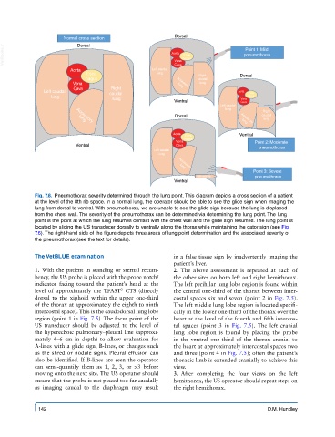
Fig. 7.8. Pneumothorax severity determined through the lung point. This diagram depicts a cross section of a patient
at the level of the 8th rib space. In a normal lung, the operator should be able to see the glide sign when imaging the
lung from dorsal to ventral. With pneumothorax, we are unable to see the glide sign because the lung is displaced
from the chest wall. The severity of the pneumothorax can be determined via determining the lung point. The lung
point is the point at which the lung resumes contact with the chest wall and the glide sign resumes. The lung point is
located by sliding the US transducer dorsally to ventrally along the thorax while maintaining the gator sign (see Fig.
7.6). The right-hand side of the figure depicts three areas of lung point determination and the associated severity of
the pneumothorax (see the text for details).
The VetBLUE examination in a false tissue sign by inadvertently imaging the
patient’s liver.
1. With the patient in standing or sternal recum- 2. The above assessment is repeated at each of
bency, the US probe is placed with the probe notch/ the other sites on both left and right hemithorax.
indicator facing toward the patient’s head at the The left perihilar lung lobe region is found within
level of approximately the TFAST CTS (directly the central one-third of the thorax between inter-
3
dorsal to the xiphoid within the upper one-third costal spaces six and seven (point 2 in Fig. 7.5).
of the thorax at approximately the eighth to ninth The left middle lung lobe region is located specifi-
intercostal space). This is the caudodorsal lung lobe cally in the lower one-third of the thorax over the
region (point 1 in Fig. 7.5). The focus point of the heart at the level of the fourth and fifth intercos-
US transducer should be adjusted to the level of tal spaces (point 3 in Fig. 7.5). The left cranial
the hyperechoic pulmonary–pleural line (approxi- lung lobe region is found by placing the probe
mately 4–6 cm in depth) to allow evaluation for in the ventral one-third of the thorax cranial to
A-lines with a glide sign, B-lines, or changes such the heart at approximately intercostal spaces two
as the shred or nodule signs. Pleural effusion can and three (point 4 in Fig. 7.5); often the patient’s
also be identified. If B-lines are seen the operator thoracic limb is extended cranially to achieve this
can semi-quantify them as 1, 2, 3, or >3 before view.
moving onto the next site. The US operator should 3. After completing the four views on the left
ensure that the probe is not placed too far caudally hemithorax, the US operator should repeat steps on
as imaging caudal to the diaphragm may result the right hemithorax.
142 D.M. Hundley