
Page 152 - Basic Monitoring in Canine and Feline Emergency Patients
P. 152
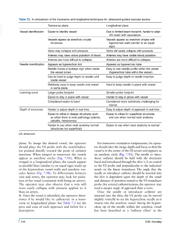
Table 7.2.  A comparison of the transverse and longitudinal techniques for ultrasound-guided vascular access.

  VetBooks.ir  Vessel identification  Transverse plane          Longitudinal plane
                                                                Due to limited beam footprint, harder to align
                             Easier to identify vessel
                                                                 US beam with vasculature
                             Vessels appear as anechoic circular   Vessels appear as anechoic stripes with
                               structures                        hyperechoic walls (similar to an equal
                                                                 sign)
                             Veins may collapse with pressure   Veins will easily collapse with pressure
                             Arteries may have visible pulsation of blood  Arteries may have visible blood pulsation
                             Arteries are more difficult to collapse  Arteries are more difficult to collapse
             Needle identification  Appears as hyperechoic dot  Appears as hyperechoic tube
                             Needle makes a bullseye sign when inside   Easy to see needle profile within the vessel
                               the vessel lumen                  (hyperechoic tube within the vessel)
                             Can be hard to judge depth of needle until   Easy to judge depth of needle insertion
                               inside vessel
                             Relatively easy to keep needle and vessel   Hard to keep needle in plane with vessel
                               in same plane
             Learning curve  Larger probe footprint             Smaller probe footprint
                             Easier to stay in plane with vessel  Harder to stay in plane with vessel
                             Considered easier to learn         Considered more technically challenging for
                                                                 novice
             Depth of structures  Harder to adjust depth in real time  Easy to adjust depth of approach in real time
                             Easier to utilize in deeper structures such   Easier to utilize for superficial structures
                               as when there is neck pathology (edema,   and use when normal neck anatomy
                               cellulitis, hematomas)
                             Harder to use when neck anatomy normal   Easier to use when neck anatomy is normal
                               (structures too superficial)
            US, ultrasound.

            plane.  To image the desired vessel, the operator   For transverse orientation venipuncture, the opera-
            should place the US probe with the notch/indica-  tor should alter the image depth and focus so that the
            tor pointed distally toward the point of catheter   vessel is in the center of the US screen and appears as
            insertion. When imaged in transverse the vessels   an anechoic circle (Fig. 7.9A). The needle or intro-
            appear as anechoic circles (Fig. 7.9A). When  in   ducer catheter should be held with the dominant
            imaged in a longitudinal plane, the vessels appear   hand and introduced through the skin 1–2 cm rostral
            as parallel lines (similar to an equal sign) made up   to the US probe and perpendicular to the indicator/
            of the hyperechoic vessel walls and anechoic vas-  notch on the linear transducer. The angle that the
            cular lumen (Fig. 7.9B). To differentiate between   needle or introducer catheter should be inserted into
            vein and artery, the operator may look for pulsa-  the skin is dependent upon the depth of the vessel
            tion of the vessel (consistent with being an artery).   and distance of insertion rostral to the US transducer
            The operator may also observe that a vein will   probe (for arterial catheterizations, the operator may
            more easily collapse with pressure applied to it   need a steeper angle of approach than a vein).
            than an artery.                               Once the needle or introducer catheter are
              4.  Once the vessel is identified, the operator deter-  inserted into the skin, the US probe can be moved
            mines if he would like to catheterize in a trans-  slightly rostrally to see the hyperechoic needle as it
            verse or longitudinal plane. See Table 7.2 for the   inserts into the anechoic vessel. Seeing the hypere-
            pros and cons of each approach and below for a   choic tip of the needle within the anechoic vessel
            description.                                 has been described as a  ‘bullseye effect’ in the


             144                                                                       D.M. Hundley