
Page 344 - Divyank Tyagi
P. 344
310 | ChAPter 8 AdvAnced Modeling And MAssing
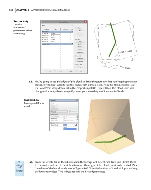
Figure 8.65
Test the
dimensional
parameters before
continuing.
16. You’re going to use the edges of this blend to drive the geometry that you’re going to create,
but since you don’t want to see this blend, turn it into a void. With the blend selected, use
the Solid/Void drop-down list in the Properties palette (Figure 8.66). The blend form will
change color to a yellow-orange if you set your visual style of the view to Shaded.
Figure 8.66
Turning a solid into
a void
17. From the Create tab in the ribbon, click the Sweep tool. Select Pick Path (not Sketch Path)
in the contextual tab of the ribbon to select the edges of the blend previously created. Pick
the edges of the blend, as shown in Figure 8.67. Note the location of the sketch plane along
the lower rear edge. This is because it is the first edge selected.
c08.indd 310 05-05-2014 16:47:50