
Page 705 - Divyank Tyagi
P. 705
|
Creating railingS 671
1. To begin, we need to build some of the components of the railing. The rail will have a
stainless steel top rail, which is already part of our default project template. However,
we will need to create the cables and the posts. Let’s start with the cable. Select the
Application button and choose New ➢ Family. Select the Profile-Rail.rft or Metric
Profile-Rail.rft family template. You’ll see two intersecting reference planes and
some text describing the Rail Centerline and the Rail Top.
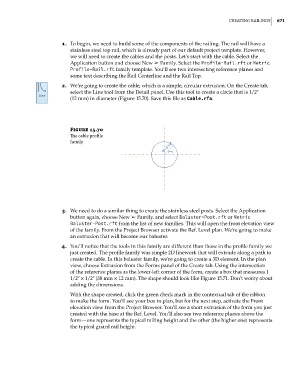
2. We’re going to create the cable, which is a simple, circular extrusion. On the Create tab,
select the Line tool from the Detail panel. Use this tool to create a circle that is 1/2ʺ
(12 mm) in diameter (Figure 15.70). Save this file as Cable.rfa.
Figure 15.70
The cable profile
family
3. We need to do a similar thing to create the stainless steel posts. Select the Application
button again, choose New ➢ Family, and select Baluster-Post.rft or Metric
Baluster-Post.rft from the list of new families. This will open the front elevation view
of the family. From the Project Browser activate the Ref. Level plan. We’re going to make
an extrusion that will become our baluster.
4. You’ll notice that the tools in this family are different than those in the profile family we
just created. The profile family was simple 2D linework that will extrude along a path to
create the cable. In this baluster family, we’re going to create a 3D element. In the plan
view, choose Extrusion from the Forms panel of the Create tab. Using the intersection
of the reference planes as the lower-left corner of the form, create a box that measures 1
1/2ʺ × 1/2ʺ (38 mm × 12 mm). The shape should look like Figure 15.71. Don’t worry about
adding the dimensions.
With the shape created, click the green check mark in the contextual tab of the ribbon
to make the form. You’ll see your box in plan, but for the next step, activate the Front
elevation view from the Project Browser. You’ll see a short extrusion of the form you just
created with the base at the Ref. Level. You’ll also see two reference planes above the
form—one represents the typical railing height and the other (the higher one) represents
the typical guard rail height.
c15.indd 671 5/3/2014 11:31:47 AM