
Page 88 - Divyank Tyagi
P. 88
54 | ChAPter 2 Applying the principles of the User interfAce And project orgAnizAtion
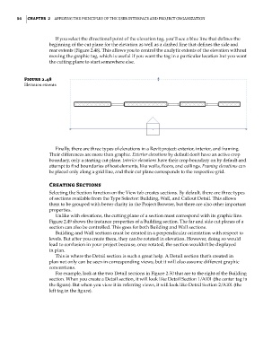
If you select the directional point of the elevation tag, you’ll see a blue line that defines the
beginning of the cut plane for the elevation as well as a dashed line that defines the side and
rear extents (Figure 2.48). This allows you to control the analytic extents of the elevation without
moving the graphic tag, which is useful if you want the tag in a particular location but you want
the cutting plane to start somewhere else.
Figure 2.48
elevation extents
Finally, there are three types of elevations in a Revit project: exterior, interior, and framing.
Their differences are more than graphic. Exterior elevations by default don’t have an active crop
boundary, only a starting cut plane. Interior elevations have their crop boundary on by default and
attempt to find boundaries of host elements, like walls, floors, and ceilings. Framing elevations can
be placed only along a grid line, and their cut plane corresponds to the respective grid.
Creating Sections
Selecting the Section function on the View tab creates sections. By default, there are three types
of sections available from the Type Selector: Building, Wall, and Callout Detail. This allows
them to be grouped with better clarity in the Project Browser, but there are also other important
properties.
Unlike with elevations, the cutting plane of a section must correspond with its graphic line.
Figure 2.49 shows the instance properties of a Building section. The far and side cut planes of a
section can also be controlled. This goes for both Building and Wall sections.
Building and Wall sections must be created in a perpendicular orientation with respect to
levels. But after you create them, they can be rotated in elevation. However, doing so would
lead to confusion in your project because, once rotated, the section wouldn’t be displayed
in plan.
This is where the Detail section is such a great help. A Detail section that’s created in
plan not only can be seen in corresponding views, but it will also assume different graphic
conventions.
For example, look at the two Detail sections in Figure 2.50 that are to the right of the Building
section. When you create a Detail section, it will look like Detail Section 1/A101 (the center tag in
the figure). But when you view it in referring views, it will look like Detail Section 2/A101 (the
left tag in the figure).
c02.indd 54 5/3/2014 10:32:11 AM