
Page 10 - Wagp_InterfaceElectronic_Volume4_2015_US.pdf
P. 10
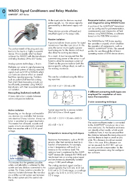
0    WAGO Signal Conditioners and Relay Modules

                ®
        JUMPLFEX  , 857 Series
    8
                                            At the input side the devices required   Parameterization, commissioning
                                            active signals, i.e., the sensor signal is   and diagnostics using WAGO-frame
                                            generated by a dedicated supply volt-  A portion of the JUMPFLEX  transducer
                                                                                                     ®
                                            age.                               can be configured for parameterization,
                                            These devices provide a filtered and   commissioning and diagnostics of field
                                            amplified signal at the output side.   devices using WAGOframe, a software
                                                                               based on the FDT/DTM standard.
                                            Passive isolation
                                                                               The WAGOframe FDT frame applica-
                                            A passive isolator draws power for signal   tion provides a wizard, which simplifies
                                            transmission from the input circuit. In this   the operation of components, such as
                                            case, the sensor must supply a power              ®
        The perfect match of housing and elec-                                 WAGO JUMPFLEX  DTMs. This wizard
        tronics is the key to a highly successful   level adequate for the device and must   guides the user through the different
        device. This is exactly what has been    also drive the working resistance.   operating modes of DTM device drivers.
        achieved by WAGO with the transducers  As a result, it must be ensured that the
        and relay modules of the 857 Series.    current-driving power of the sensor is suf-
                                            ficient to drive the maximum current of
        Analog systems technology — Basics   20mA via the passive isolator (with the
                                            device-specific voltage drop), as well as
        Problems can arise in signal processing
        in industrial systems of analog standard   the working resistance.
        signals (such as 0-10V or 0-20mA) which
        can have an adverse effect on overall
        fault-free signal processing. Problems   This can be calculated using the follow-
        such as potential differentials arising   ing equation:
        from interlinked measuring circuits can
        be efficiently prevented using WAGO
        transducers, with their associated electri-  US ≥ UE = UV + 20 mA x RB
        cal isolation.
        Decoupling (Isolation) methods           US                            3 different connecting techniques are
                                                                               employed for acquisition of resis-
        A basic distinction is made between                     I  UE  ____>     I           I  RB  tance thermometers:
        active and passive isolation.

                                                                               2-wire connecting technique
                                                       __________________>
                                                          UV = 2.0 V
                                                                                            1
        Active isolation                    Typical equation for a passive isolator         2
                                            (857-451) for a 20mA signal.                    3
        Depending on the design and model in                                               4
        use, devices are available that incorpo-
        rate electrical 3-way isolation. 4-way iso-  US ≥ UE = 2.0 V + 20 mA x 600 Ω          2-wire
        lation is provided in a signal duplicator.
        This means that all inputs, outputs and   US ≥ UE = 14 V               The resistance thermometer is connected
                                                                                            ®
        supply circuits are electrically isolated                              to the JUMPFLEX  transducer via a two-
        from one another with a 2.5 kV proof                                   wire conductor. As the feed-in resistance
        voltage.                                                               can directly affect results, which would
                                            Temperature measuring techniques   invalidate them, it must be ensured that
                                                                               the distance between the measuring point
                                            Resistance thermometers, such as Pt100   and the device is kept as small as pos-
                                            sensors, alter their resistance level as a   sible. This distance should not exceed
                                            function of temperature. For example,   10m in this case. If this distance can
                                            a rise in temperature will result in an   not be ensured, the 857-801 unit can
                                            increase in the resistance level. This   be used provide compensation for the
                                            reistance level is registered by the JUMP-  incoming resistance using the configura-
                                            FLEX  devices (for example 857-800) and   tion software.
                                               ®
          2.5 KV                            transformed into an analog output signal
          Safe Isolation
                                            and simultaneously electrically isolated
        This ensures that the greatest possible   using a 2.5kV proof voltage.
        safety and reliability is achieved for the   The analog standard signal can be a
        system and any devices connected to the  current signal in the 0-20 mA, 4-20 mA
        system. For 3-way isolation provides for   0-10 mA or 2-10 mA range, or a voltage
        electrical isolation between the transduc-  signal in the 0-10 V, 2-10 V, 0-5 V or
        ers and the control system and between   1-5 V range.
        the control system and the control ele-
        ments.