
Page 13 - Wagp_InterfaceElectronic_Volume4_2015_US.pdf
P. 13
0
11
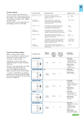
Contact material
Contact material Properties and use Range of values
To ensure a long service life and low
contact resistance, various materials may Ag Ni 0.15 + 5 μ Au High corrosion resistance, low and μV . . . 30 V
be used for relay contacts (depending on constant contact resistance at small power μA . . . 0.2 A
ratings, for dry circuits
the load type, switching current, voltage
and duty cycle). Ag Ni plated Same properties as a 5 μ gold contact, 100 mV/10 μA
with Au Ag + Au
however with five times greater resistance
Possible mate rials, their properties and to wear, for all circuits from the μW range
advantages are shown in the table. up to 100 W/1 kVA
Ag Cd 0 + 1 μ Au Low tendency to contact weld, high resistance ≥ 5 V
to contact burn-out at higher power rating, ≥ 10 mA
also suitable for lower power ratings
Ag Cd 0, Low tendency to contact weld, high resistance ≥ 12 V
with gold flash to contact burn-out at higher power rating, with ≥ 100 mA
gold flash for additional protection during storage
Ag Ni 0.15 + HV High mechanical strength, low tendency to ≥ 12 V
contact weld and low contact resistance, universal 5 mA – 10 A
application at medium loads
Ag Sn 0 2 Small tendency to contact weld, high resistance to ≥ 5 V/100 mA
contact burn-out at higher power rating, small ≥ 10 V/10 mA
migration of material, for circuits with high input ≥ 24 V/1 mA
and output ratings, DC circuits
–3
Ag alloy, High mechanical strength, small tendency to 10 W
with gold flash contact weld, wide scope of application for low to
medium ratings
Contact switching protection Additional Defined Attenuation Advantages /
When switching inductive loads Switching of load off-delay limitation of when used disadvantages
inductive with bipolar
(e.g., for contractors or solenoid valves) voltage circuits
transients with peak voltages up to Circulating diode Advantages:
thousands of volts will arise. • simple device
+ • cost-effective, reliable
Suppression is necessary as these • sizing not critical
transients frequently exceed admissible large yes (V D ) no • small inductive voltages
EMC limits. <__________ U D Load Disadvantages:
Moreover, they cause electric arcs at the – • limit only via load
resistance
switching contact that destroy the • longer turn-off time
contact and significantly reduce the Series of diode /Zener diode Advantages:
relay’s service life and functional safety. • sizing not critical
+ Disadvantages:
In practical use the following switching • limits only above V ZD
protections, which are connected directly Load medium yes (V ZD ) no
to small
at the source in parallel to the load, have <__________ U ZD
proved to be efficient: –
Suppressor diode Advantages:
• cost-effective
+ • sizing not critical
limitation of positive peaks
• • suitable for alternating
<__________ U ZD Load medium yes (V ZD ) yes voltages
to small Disadvantages:
– • attenuation only
above V ZD
Varistor Advantages:
• high energy absorption
+ • sizing not critical
• suitable for AC voltages
<__________ U VDR Load to small
medium yes (V VDR ) yes Disadvantages:
VDR
• attenuation only
– above V VDR
R/C combination Advantages:
• limiting by energy storage
+ • suitable for
alternating voltages
medium no yes • limiting independent
R
__________> Load to small of level
U RC
C Disadvantages:
– • exact component values
• high turn-on current pulse