
Page 11 - Wagp_InterfaceElectronic_Volume4_2015_US.pdf
P. 11
0
9
Compensation for line resistance drop for the incoming and outgoing Cold-junction compensation can be acti-
(2-wire) lines can be measured separately and vated and de-activated just by a click
compensation provided for as required. using the configuration software (default
A resistance value can be input into this Again, no line adjustment is required setting: ON (activated)).
field for compensation of the line resis- here.
tance for 2-wire sensors within a range of Table for Thermocouples
0-50 Ω . Thermocouples
Adjusting the values for resistance com-
pensation is only possible by setting the In contrast to resistance thermometers,
sensor wire connection to 2-wire. Other- thermocouples are active sources that
wise the field is displayed in gray and generate output in the microvolts range.
no values can be entered. Using 3- and Thermocouples have very low resistance
4-wire sensors, the input cable resistance and are therefore noise-free. Preferred
is compensated via the connection tech- applications include tasks in environments
nology and does not enter into the mea- with high temperatures, such as in ovens
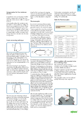
suring results. or machines in the plastics industry. Type of Thermocouple Measuring range
The joining of two different materials sensor materials
at the thermocouple results in different J *) Fe-CuNi -210 °C ... +1200 °C
3-wire connecting technique energy of formation of the metal atom
electrons, yielding a thermoelectric volt- K *) NiCr-Ni -200 °C ... +1372 °C
E *) NiCr-CuNi -200 °C ... +1000 °C
1 age. The level of this thermoelectric volt-
2 age is a function of the material and of N *) NiCrSi-NiSi -200 °C ... +1300 °C
3 temperature. R *) Pt13Rh-Pt +250 °C ... +1768 °C
S *) Pt10Rh-Pt -50 °C ... +1664 °C
4
Fe Cu
T *) Cu-CuNi -200 °C ... +400 °C
3-wire
_____> B *) Pt30Rh-Pt6Rh +250 °C ... +1820 °C
The 3-wire connecting technique mini- 1 2 C
mizes the effect of line resistance. The 0 °C ... +2320 °C
resistance thermometer is gauged via two CuNi Cu *) Thermocouples based on IEC 584 / EN 60584
measuring circuits implemented in the Other thermocouples available upon request.
®
JUMPFLEX transducer. One measuring If the temperature at measuring point ϑ1 is
circuit serves as the reference circuit. Line the same as the temperature at reference Relay modules with mounted minia-
resistance can be compensated for in this point ϑ2, no current will flow, as the two ture switching relays
manner. component voltages cancel one another out. The JUMPFLEX product family is
®
The measuring results can, however, However, if the temperatures at the measur- rounded out by the relay modules that fit
nevertheless be affected by different line ing point and at the reference point are dif- perfectly with the transducers.
lengths or by different ambient tempera- ferent, differing voltage levels are produced
tures. No further line adjustment is usually which do not completely cancel one another A logical enclosure concept with options
necessary, as the same line lengths and out, resulting in a flow of current. for linking all levels offers a variety of
the same ambient temperatures exist in synergy and cost-savings potential. This
most cases. To summarize then, a thermocouple only allows for efficient optimization of instal-
measures a difference in temperature. This is lation efforts.
yielded from the difference between the ther-
moelectric voltage levels at the measuring The pluggable relays can be replaced
point and at the reference point. The voltage quickly and easily when required.
fluctuation produced by the thermoelectric
4-wire connecting technique effect is very low and is generally only a few
microvolts per Kelvin. Therefore, only the dif-
1
ference between the thermoelectric voltages
2
of the materials used is of significance, for
3
example, thermocouple type J, iron (Fe) and
4 constantan (CuNi).
4-wire
Also of some significance in the connec-
tion point temperature. This temperature
The most accurate measuring method
employs the 4-wire connecting technique. must be known in order to derive the
This involves feeding in a low supply ambient temperature from the thermoelec-
current via two fully isolated measur- tric voltage level. This is why the tempera-
ing circuits via two lines and measuring ture at the connection point is measured
®
the voltage drop across the resistance by JUMPFLEX transducers. This value,
thermometer via the other two lines. This also referred to as the reference or cold
method offers the advantage not being junction, can then be compensated for.
influenced by line resistance or tempera- (cold junction compensation)
ture-induced fluctuations, as the voltage