Page 15 - Wagp_InterfaceElectronic_Volume4_2015_US.pdf
P. 15

WAGO Optocouplers                                                                                        0

                                                                                                                   13
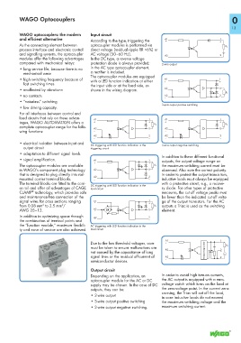
           WAGO optocouplers: the modern      Input circuit
           and efficient alternative
                                              According to the type, triggering the   A1                      1
                                                                                   +
                                                                                                              +
           As the connecting element between   optocoupler modules is performed via
           process interface and electronic control   direct voltage (residual ripple RR <6%) or                R L
           and signalling systems, the optocoupler   AC voltage (50–60 Hz).
                                                                                                              2
                                                                                  A2
           modules offer the following advantages   In the DC type, a reverse voltage     –                   –
           compared with mechanical relays:   protection diode is always provided;    2-wire output
           •  long service life, because there is no   in the AC type optocoupler element,
             mechanical wear                  a rectifier is included.
                                              The optocoupler modules are equipped
           •  high switching frequency because of   with a LED function indication at either   A1            1
             fast switching times             the input side or at the load side, as   +                     +
           •  unaffected by vibrationn        shown in the wiring diagram.        A2                         3
                                                                                  –

                                                                                                                R L
           •  no contacts                                                         A2                         2
                                                                                  –                          –
           • “noiseless” switching
                                                                                 3-wire output positive switching
           •  low driving capacity.
           For all interfaces between control and
           load circuits that rely on these advan-
                                               A1                         1       A1                          1
           tages, WAGO AUTOMATION offers a     +                          +       +                           +
           complete optocoupler range for the follo-                         R L                                R L
                                               A2                         3       A2                          3
           wing functions:                     –                                  –
                                               A2                         2       A2                          2
                                               –                          –       –                           –
           •  electrical isolation between input and   DC triggering with LED function indication in the  3-wire output negative switching
             output circuit                   triggering circuit
           •  adaptation to different signal levels
                                                                                 In addition to these different functional
           •  signal amplification.            A1                         1      outputs, the output voltage range an
           The optocoupler modules are available   +                      +   R L   the maximum switching current must be
           in WAGO’s component plug technology   A2                       3      observed. Also note the correct polarity.
           that is designed to plug directly into rail-  –                       In order to protect the output transis tors,
           mounted carrier terminal blocks.    A2                         2      inductive loads must always be equipped
                                               –
                                                                          –
           The terminal blocks are fitted to the carri-                          with a protective circuit, e.g., a recove-
                                              DC triggering with LED function indication in the
           er rail and offer all advantages of CAGE   load circuit               ry diode. For other types of protective
                 ®
           CLAMP  technology, which provides safe                                measures, the cut-off voltage peaks must
           and maintenance-free connection of the                                be lower than the indicated cut-off volta-
           signal wires for cross sections ranging   A1                   1      ge of the output transistors. For the AC
                                2
                      2
           from 0.08 mm  to 2.5 mm /            ~                         +   R L   outputs a Triac is used as the switching
           AWG 28–12.                          A2                         3      element.
                                                ~

           In addition to optimizing space through
                                               A2                         2
           the combination of terminal points and    ~                    –
           the “function module,” maximum flexibili-  AC triggering with LED function indication in the
           ty and ease of service are also achieved.   load circuit
                                              Due to the low threshold voltages, care   A1                    ~
                                                                                                              1
                                                                                   +
                                              must be taken to ensure malfunctions are                           R L
                                              not caused by the capacitance of long   A2              Nullspannungsschalter   2
                                                                                   –
                                                                                                                ~
                                              signal lines or the residual off-current of   A2                  2    ~
                                              semiconductor devices.               –                            ~

                                              Output circuit
                                              Depending on the application, an    In order to avoid high turn-on currents,
                                              optocoupler module for the AC or DC   the AC output is equipped with a zero-
                                              supply may be chosen. In the case of DC   voltage switch which turns on the load at
                                              outputs, they can be:              the zero-voltage point. In the current zero-
                                                                                 crossing, the Triac will cut off the load,
                                              •  2-wire output
                                                                                 in case inductive loads do not exceed
                                              •  3-wire output positive switching  the maximum switching voltage and the
                                              •  3-wire output negative switching.  maximum switching current.
   10   11   12   13   14   15   16   17   18   19   20