
Page 14 - Wagp_InterfaceElectronic_Volume4_2015_US.pdf
P. 14
0 WAGO Relay Modules
12
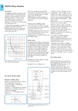
Service life After removing the control signal, the As shown in the fig. “Example of Circuit
The difference between mechanical life relay returns to its respective position and Configuration,“ two SF relays are con-
and electrical life must be distinguished. can only be switched over by a control trolled by one output interface. The NO
Mechanical life consists the amount of signal circuit. The bistable contacts 13–14/19–20 of relay A and
switching operations without contact switching relays are only available for B switch over the peripheral equipment.
load; electrical life at maximum load direct voltage with positive or negative After switching off equipment a ... d the
refers to the amount of switching triggering. control circuit
operations with maximum switching capa- (NC contacts 5–6/11–12) verifies that
city and resistive load. Current pulse switching relay all main circuits are interrupted.
Smaller switching capacities increase the One current pulse is needed to change When the control circuit is closed, the
operation at maximum load. The the relay from the rest position to the wor- next operation cycle will be executed by
following illustration shows the typical king position and vice versa. the CPU or by the control logic.
course between switching current and Depending on the safety requirements,
relay's operational life. During the triggering process, one of two an open control circuit prevents
status indicators displays the actual con- operation of either the entire machine or
tact position. The current pulse specified components.
switching relay is available for direct and If a partial or complete standstill is
alternating voltage.
1000 required in the event of a failure
(for ex. in medical technology or chemi-
500 Safety relay cal processes) each control contact can
Live x 10 4 switching operations 200 250VAV, resistive load increasingly recommended and specified Independent of a single or complete
be polled and evaluated.
Force-guided safety relays, have become
control for the NO contact, the SF relay
for self-regulated systems as they provide
operates in such a way that the other
protection for personnel, machines and
100
250VAC, inductive load
equipment is switched off even if a NO
installations. Relays with force-guided
(cos.ϕ = 0.4)
50
contact is welded. The failure is recogni-
contacts are an essentially safety com-
ponent for these circuits, particularly
20
contacts are still able to open to interrupt
when defects occur. WAGO offers these
circuits.
10
functions in special relay modules with zed by the control contact while the other
force-guided contacts as based on to
1 2 3 4 5 6 7 8 9 10 ZH1/457 Time delay relays
Switching current A
(Specification of the employer’s liability
insurance association). WAGO time delay relay modules are
More details upon request.
electromechanical time relays with an
Example of circuit configuration: integrated time response, e.g., acc. to
VDE 0435, part 201/5.83.
The time ranges can be adjusted via
potentiometer for either continuously
variable or linear operation. A status LED
Input interface indicates the switching condition of the
relay.
CPU
Description of select relays or
control logic
Monitoring circuit
Bistable switching relays Output interface
Bistable switching relays have 3 coil con-
tacts. According to the wiring
scheme, the relay is switched into
B
“working condition“ 20 a
19
(contacts 11–14 closed) by the common 12
connection A 3 and the connection A 1 11 13 b
and into “rest position“ 14 5
(contacts 11–14 opened) by the con- 6
nection A 2. A 20
19 c
12
11
A1 13
+ 11 d
14
5
A3 _ 6
12
A2
+ 14
Control of different peripheral equipment (a, b, c, d)
with monitoring