
Page 445 - Wagp_InterfaceElectronic_Volume4_2015_US.pdf
P. 445
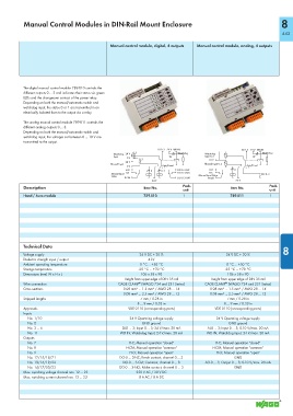
Manual Control Modules in DIN-Rail Mount Enclosure                                                      8


                                                                                                                    443
                                              Manual control module, digital, 4 outputs  Manual control module, analog, 4 outputs


           The digital manual control module 789-810 controls the
           different outputs 0 ... 3 and indicates their status via green
           LEDs and the changeover contact of the power relay.
           Depending on both the manual/automatic switch and
           watchdog input, the states 0 or 1 are transmitted in an
           electrically isolated from to the output via a relay.
           The analog manual control module 789-811 controls the
           different analog outputs 0 ... 3.
           Depending on both the manual/automatic switch and
           watchdog input, the voltages set between 0 ... 10 V are
           transmitted to the output.
                                                                 DI 0..3 24 V WD-IN
                                                                                                   AI 0..3 24 V WD-IN
                                                       0..3                                                Watchdog
                                                                         Watchdog
                                                    24 V                            Watchdog-
                                               Watchdog-
                                                                                    Input 0..3
                                               Input                  W                                 W
                                                    0 V
                                                         0..3
                                                                                      10 V
                                                    24 V
                                                                                    Manual Input 0..3
                                              Manual Input
                                                                                                     Auto/Hand
                                                                   Auto/Hand
                                                    0 V
                                                    H-O                               H-O       H
                                                                         DO 0..3-NC
                                                              H   0..3
                                                    H-C                  DO 0..3-NO   H-C
                                              Manual Input
                                                                                                           AO 0..3
                                                                                  Manual Input Status
                                              Status
                                                    H-CM                 DO 0..3-CM
                                                                                     H-CM
                                                               24 V                              24 V
           Description                                     Item No.        Pack.               Item No.       Pack.
                                                                           unit                               unit
           Hand / Auto module                              789-810         1                   789-811        1
                                                                                                                    8
           Technical Data                                                                                           8
           Voltage supply                                 24 V DC ± 20 %                     24 V DC ± 20 %
           Dielectric strength input / output                4 kV
           Ambient operating temperature                  0 °C ... +50 °C                    0 °C ... +50 °C
           Storage temperature                           -25 °C ... +70 °C                  -25 °C ... +70 °C
           Dimensions (mm) W x H x L                      106 x 58 x 90                      106 x 58 x 90
                                                   Height from upper-edge of DIN 35 rail  Height from upper-edge of DIN 35 rail
                                                         ®
                                                                                             ®
           Wire connection                       CAGE CLAMP  (WAGO 734 and 231 Series)  CAGE CLAMP  (WAGO 734 and 231 Series)
           Cross sections                          0.08 mm² ... 1.5 mm² / AWG 28 ... 14  0.08 mm² ... 1.5 mm² / AWG 28 ... 14
                                                   0.08 mm² ... 2.5 mm² / AWG 28 ... 12  0.08 mm² ... 2.5 mm² / AWG 28 ... 12
           Stripped lengths                               7 mm / 0.28 in                     7 mm / 0.28 in
                                                         8 ... 9 mm / 0.33 in               8 ... 9 mm / 0.33 in
           Approvals                                 VDE 0110 (corresponding parts)     VDE 0110 (corresponding parts)
           Inputs
            No. 1/10                                  24 V Operating voltage supply      24 V Operating voltage supply
            No. 2                                          GND ground                         GND ground
            No. 3 ... 6                            DI-0 ... 3; Input 0 ... 3; 24 V/max. 20 mA  AI-0 ... 3; Input 0 ... 3; 0-10 V/max. 20 mA
            No. 11                                WD-IN; Watchdog input; 24 V/max. 20 mA  WD-IN; Watchdog input; 24 V/max. 20 mA
           Outputs
            No. 7                                    H-C; Manual operation "closed"      H-C; Manual operation "closed"
            No. 8                                   H-CM; Manual operation "common"    H-CM; Manual operation "common"
            No. 9                                     H-O; Manual operation "open"       H-O; Manual operation "open"
            No. 12/15/18/21                       DO-0 ... 3-NC; Break contact; channel 0 ... 3  GND
            No. 13/16/19/22                        DO-0 ... 3-CM; Common; channel 0 ... 3  AO-0 ... 3; Output 0 ... 3; 0-10 V/max. 20 mA
            No. 14/17/20/23                       DO-0 ... 3-NO; Make contact; channel 0 ... 3  GND
           Max. switching voltage channel nos. 12 ... 23  250 V AC / 30 V DC
           Max. switching current channel nos. 12 ... 23  8 A AC / 8 A DC