
Page 133 - GIGABYTE Service Manual-v3.0-110101
P. 133
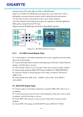
enjoyment from DVD audio, Blu-ray DVD, or HD DVD discs.

                   Support for 16/20/24-bit S/PDIF input and output offers easy connection of PCs to
                   high-quality consumer electronic products such as digital decoders and speakers.
                   Two jack detection pins each designed to detect up to 4 jacks Supports
                   Up to four channels of microphone array input are supported for AEC/BF application

                   High-quality analog differential CD input
                   Supports external PCBEEP input and built-in digital BEEP generator.


                                         Figure 8-4: ALC889A Hardware Features


                   8.2.2     ALC889A Sound Repair Steps


                   01. Visually inspect on all related components, like resistor, capacitor around the Sound
                   chip to see if any damage.

                   02. Touch sound chip surface by hand to feel temperature of the chip. If chip is burn out
                   already, you’ll feel chip is very hot.
                   03. Check Sound connector to see if any pin is bent, short, missed or poorly soldered.
                   04. Check Sound setting in CMOS SETUP and set DEFAULT CMOS SETTINGS.
                   05. Check all voltages on Sound chip pins VCC3 (Fuse) AVDD=5V (Transistor),

                   VREF (2.4V).
                   06. Check Sound Clock: BIT_CLK, –ACZRST, ACZ_SYNC, ACZ_SDOUT,
                   ACZ_SDIN2.


                   8.3  IEEE1394 Repair Steps

                   01. Visually inspect on all related components around the TSB43AB23 chip to see if
                   any damage.

                   02. Touch control chip surface by hand to feel temperature of the chip. If chip is burnt
                   out already, you’ll feel the chip is very hot.
                   03. Check IEEE 1394 connector to see if any pin is bent, short, missed or poorly
                   soldered.

                   04. Check IEEE 1394 settings in CMOS SETUP and set DEFAULT CMOS


                                                           111