
Page 16 - Станочный парк английская версия
P. 16
METALWORKING EQUIPMENT AND TOOLS
Substantiation of the design of the block boring tool
The aim of the development is to increase the efficiency of boring of body
parts in the conditions of flexible production on the basis of multi-purpose CNC
machines
In such a production, the variety of
machined parts and the technology for
processing precise holes in these parts
require a large number of boring mandrels,
both on machines and in the warehouse. For
example, a set of mandrels for machining
parts such as "feed box" of a 16K20 lathe
includes 34 mandrels.
Therefore, it is advisable to use a
block boring tool (BBT), which consists of
interchangeable functional blocks, which, in
various permutations, allows you to create
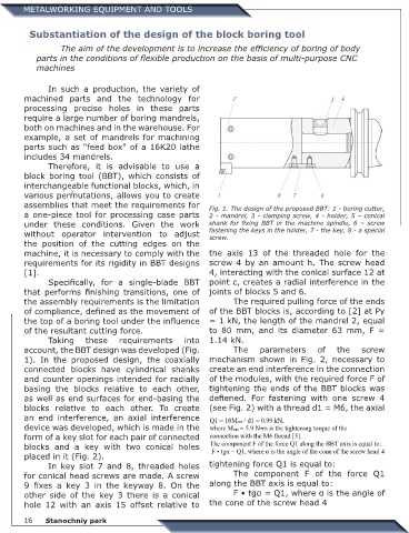
assemblies that meet the requirements for Fig. 1. The design of the proposed BBT: 1 - boring cutter,
a one-piece tool for processing case parts 2 - mandrel, 3 - clamping screw, 4 - holder, 5 – conical
under these conditions. Given the work shank for fixing BBT in the machine spindle, 6 – screw
without operator intervention to adjust fastening the keys in the holder, 7 - the key, 8 - a special
screw.
the position of the cutting edges on the
machine, it is necessary to comply with the the axis 13 of the threaded hole for the
requirements for its rigidity in BBT designs screw 4 by an amount h. The screw head
[1]. 4, interacting with the conical surface 12 at
Specifically, for a single-blade BBT point c, creates a radial interference in the
that performs finishing transitions, one of joints of blocks 5 and 6.
the assembly requirements is the limitation The required pulling force of the ends
of compliance, defined as the movement of of the BBT blocks is, according to [2] at Py
the top of a boring tool under the influence = 1 kN, the length of the mandrel 2, equal
of the resultant cutting force. to 80 mm, and its diameter 63 mm, F =
Taking these requirements into 1.14 kN.
account, the BBT design was developed (Fig. The parameters of the screw
1). In the proposed design, the coaxially mechanism shown in Fig. 2, necessary to
connected blocks have cylindrical shanks create an end interference in the connection
and counter openings intended for radially of the modules, with the required force F of
basing the blocks relative to each other, tightening the ends of the BBT blocks was
as well as end surfaces for end-basing the defiened. For fastening with one screw 4
blocks relative to each other. To create (see Fig. 2) with a thread d1 = M6, the axial
an end interference, an axial interference
device was developed, which is made in the
form of a key slot for each pair of connected
blocks and a key with two conical holes
placed in it (Fig. 2).
In key slot 7 and 8, threaded holes tightening force Q1 is equal to:
for conical head screws are made. A screw The component F of the force Q1
9 fixes a key 3 in the keyway 8. On the along the BBT axis is equal to:
other side of the key 3 there is a conical F • tgα = Q1, where α is the angle of
hole 12 with an axis 15 offset relative to the cone of the screw head 4
Stanochniy park