
Page 912 - Chief Architect Reference Manual
P. 912
Chief Architect X10 Reference Manual
3D Molding Polyline Tool
Select Build> Trim> 3D Molding Floor Plan View
Polyline in floor plan or cross section/
elevation view to create a closed molding
polyline.
Cross Section/
• When drawn in a cross section/elevation Elevation View
view, a 3D Molding Polyline’s top and (selected)
bottom edges have two different heights.
Its sides have different heights at their 3D Overview
start and end points.
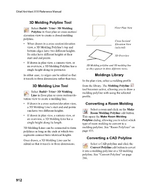
• If drawn in plan view, a camera view, or
an overview, a 3D Molding Polyline has a 3D Molding polyline and 3D molding line
single height along its perimeter. as they appear in three different views.
In either case, its edges can be edited so that Moldings Library
it travels in three dimensions rather than two.
In the plan view, select a molding profile
3D Molding Line Tool from the library. The Molding Polyline
tool becomes active, allowing you to draw a
Select Build> Trim> 3D Molding molding polyline with using the selected
Line in floor plan or cross section/ele- profile.
vation view to create a molding line.
• If drawn in a cross section/elevation view, Converting a Room Molding
a 3D Molding Line’s start and end points
can have two different heights. Select a room and click on the Make
Room Molding Polyline edit button.
• If drawn in plan view, a camera view, or This opens the Make Room Molding
an overview, a 3D Molding Line has a Polyline dialog, allowing you to select which
single height along its length. type of room molding to convert to a
3D Molding Lines can be connected to form molding polyline. See “Room Polylines” on
polylines as long as the ends at which two page 433.
segments connect have identical heights.
Converting a CAD Polyline
Once drawn, a 3D Molding Line can be
edited so that it travels in three dimensions. Select a CAD polyline and click the
Convert Polyline edit button to covert
it into a molding polyline or a 3D molding
polyline. See “Convert Polyline” on page
266.
912