
Page 141 - FreesStyler® Installation and Startup
P. 141
®
INSTALLATION AND STARTUP
Chapter 9 Optional “Add-On” Items
Triple Foam Option for Pulsatron Pump System
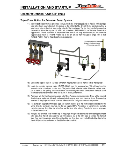
14) Next will be to install the main pneumatic hookups. Inside the driver side pod and on the side of the carriage
plate is the 3-port pneumatic stack. It is located on the right end of the din rail. On the standard machine a
soap foamer valve is already in place on the left end of the 3-port valve. The first thing to do before mounting
the valve is to tighten the supplied 1/8” NPT x 3/8” tube elbow (1ELBOW-PL250) into the valve. The elbow is
supplied with Teflon® tape which is only needed here. Next to the soap foamer valve you will mount the
supplied valve mount kit (1VALVE-PN332) first to the din rail and then the supplied single valve to that
(1VALVE-PN331). Refer to the pictures for more assistance.
This electrical junction box is
located in the driver side pod
of the carriage assembly
15) Connect the supplied 3/8 x 38-1/2” clear airline from the pneumatic valve to the feed side of the regulator.
16) Locate the supplied electrical cable (1ELECT-CB888) from the accessory box. This will run from the
pneumatic valve to the 8-port junction block. The junction block is located on the driver side carriage plate,
just to the left of the opening from the utility hole. Screw and tighten the din connector on the cable to the
pneumatic valve and connect the other end to port #1 on the junction block.
17) Purchased with the triple foam option was a set of three Pulsatron pump assemblies. These will be mounted
directly to your equipment side wall, preferably just above your triple foam chemical drums. The mounting
fasteners for the pumps and the 3/8” chemical lines that will run through the boom are not provided.
18) The pumps are supplied with the cord grips and washers that will go to the electrical connection box for the
wiring. Once the pumps are mounted, run the two supplied 3/8” x 7ft. sections of tubing from the pump to
inside the chemical drum. One line is the feed and the other is for priming. Refer to the pictures for proper
routing and instructions.
19) Run your 3/8” chemical lines from the top of the pumps through both booms and to the carriage bulkhead
utility plate. Use the 3/8” bulkheads that are in the second row of the utility plate to connect the chemical
lines. Now from the opposite side of the utility plate, run three lines from the bulkhead utility plate to the
chemical injectors that are located on the triple foam feed manifold.
1MANUL220 Belanger, Inc. * 1001 Doheny Ct. * Northville, MI 48167 * Ph (248) 349-7010 * Fax (248) 380-9681 9-9