
Page 247 - Saber® Installation & Startup
P. 247
INSTALLATION & STARTUP
Chapter 22 Initial Startup Procedure
Startup Procedure
Check I/O and Motion
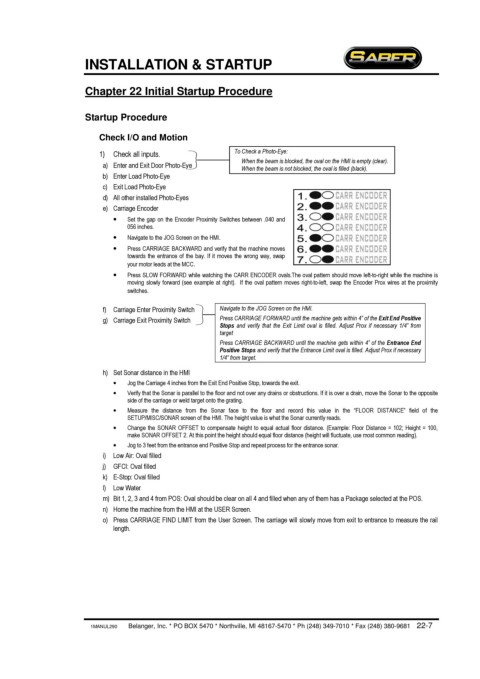
1) Check all inputs. To Check a Photo-Eye:
When the beam is blocked, the oval on the HMI is empty (clear).
a) Enter and Exit Door Photo-Eye When the beam is not blocked, the oval is filled (black).
b) Enter Load Photo-Eye
c) Exit Load Photo-Eye
d) All other installed Photo-Eyes
e) Carriage Encoder
· Set the gap on the Encoder Proximity Switches between .040 and
056 inches.
· Navigate to the JOG Screen on the HMI.
· Press CARRIAGE BACKWARD and verify that the machine moves
towards the entrance of the bay. If it moves the wrong way, swap
your motor leads at the MCC.
· Press SLOW FORWARD while watching the CARR ENCODER ovals.The oval pattern should move left-to-right while the machine is
moving slowly forward (see example at right). If the oval pattern moves right-to-left, swap the Encoder Prox wires at the proximity
switches.
f) Carriage Enter Proximity Switch Navigate to the JOG Screen on the HMI.
g) Carriage Exit Proximity Switch Press CARRIAGE FORWARD until the machine gets within 4” of the Exit End Positive
Stops and verify that the Exit Limit oval is filled. Adjust Prox if necessary 1/4” from
target
Press CARRIAGE BACKWARD until the machine gets within 4” of the Entrance End
Positive Stops and verify that the Entrance Limit oval is filled. Adjust Prox if necessary
1/4” from target.
h) Set Sonar distance in the HMI
· Jog the Carriage 4 inches from the Exit End Positive Stop, towards the exit.
· Verify that the Sonar is parallel to the floor and not over any drains or obstructions. If it is over a drain, move the Sonar to the opposite
side of the carriage or weld target onto the grating.
· Measure the distance from the Sonar face to the floor and record this value in the “FLOOR DISTANCE” field of the
SETUP/MISC/SONAR screen of the HMI. The height value is what the Sonar currently reads.
· Change the SONAR OFFSET to compensate height to equal actual floor distance. (Example: Floor Distance = 102; Height = 100,
make SONAR OFFSET 2. At this point the height should equal floor distance (height will fluctuate, use most common reading).
· Jog to 3 feet from the entrance end Positive Stop and repeat process for the entrance sonar.
i) Low Air: Oval filled
j) GFCI: Oval filled
k) E-Stop: Oval filled
l) Low Water
m) Bit 1, 2, 3 and 4 from POS: Oval should be clear on all 4 and filled when any of them has a Package selected at the POS.
n) Home the machine from the HMI at the USER Screen.
o) Press CARRIAGE FIND LIMIT from the User Screen. The carriage will slowly move from exit to entrance to measure the rail
length.
1MANUL290 Belanger, Inc. * PO BOX 5470 * Northville, MI 48167-5470 * Ph (248) 349-7010 * Fax (248) 380-9681 22-7