
Page 82 - DryLite® Dryers
P. 82
®
DRYLITE DRYER
Chapter 7: Utilities for DryLite®
Air Connections: Air Panels to Top Flip and Side Flip Cylinders
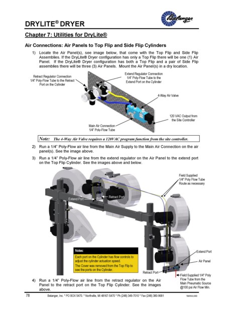
1) Locate the Air Panel(s), see image below, that come with the Top Flip and Side Flip
Assemblies. If the DryLite® Dryer configuration has only a Top Flip there will be one (1) Air
Panel. If the DryLite® Dryer configuration has both a Top Flip and a pair of Side Flip
assemblies there will be three (3) Air Panels. Mount the Air Panel(s) in a dry location.
Extend Regulator Connection
Retract Regulator Connection 1/4” Poly-Flow Tube to the
1/4” Poly-Flow Tube to the Retract Extend Port on the Cylinder
Port on the Cylinder
4-Way Air Valve
120 VAC Output from
the Site Controller
Main Air Connection
1/4” Poly-Flow Tube
Note: The 4-Way Air Valve requires a 120VAC program function from the site controller.
2) Run a 1/4” Poly-Flow air line from the Main Air Supply to the Main Air Connection on the air
panel(s). See the image above.
3) Run a 1/4” Poly-Flow air line from the extend regulator on the Air Panel to the extend port
on the Top Flip Cylinder. See the images above and below.
Field Supplied
1/4" Poly Flow Tube
Route as necessary
Retract Port
Extend Port
Notes: Extend Port
Each port on the Cylinder has flow controls to
adjust the cylinder actuation speed. Air Panel
The Cover was removed from the Top Flip to
see the ports on the Cylinder.
Retract Port
Field Supplied 1/4" Poly
4) Run a 1/4” Poly-Flow air line from the retract regulator on the Air Flow Tube from the
Panel to the retract port on the Top Flip Cylinder. See the images Main Pneumatic Source
@100 psi Air Flow Min.
above.
78 Belanger, Inc. * PO BOX 5470. * Northville, MI 48167-5470 * Ph (248) 349-7010 * Fax (248) 380-9681 1MANUL960