
Page 17 - Gyro Wrap™ Signature ® Series
P. 17
GYRO WRAP™ Signature ® Series
Installation
Tunnel Placement
When placing a piece of equipment, tunnel depth will vary from site to site. Be sure to allow an
adequate operating envelope when installing. Use the physical dimensions from pages 9 and 10 to
help determine placement.
Do all work in the approximate area where you will permanently place the Gyro Wrap™.
Frame Assembly
1) Measure, square up, and run a chalk line down the center of the wash bay relative to the doors or
entrance as shown below. The actual length down the bay will vary from site to site. Write down this
dimension from your site plan drawings.
2) Remove the Head Beam Assembly and both of the Leg Assemblies from the skid. Locate the accessory
box and remove all of the 1/2-13 x 3” hex head fasteners along with all of the 1/2” lock washers. Also
remove all of the 5/8” x 6” lag bolts.
3) Using a forklift, secure the head beam assembly to the forks using two C-Clamps.
Note: Be sure to use protective material on the head beam assembly so that you do not
scratch the powder coating.
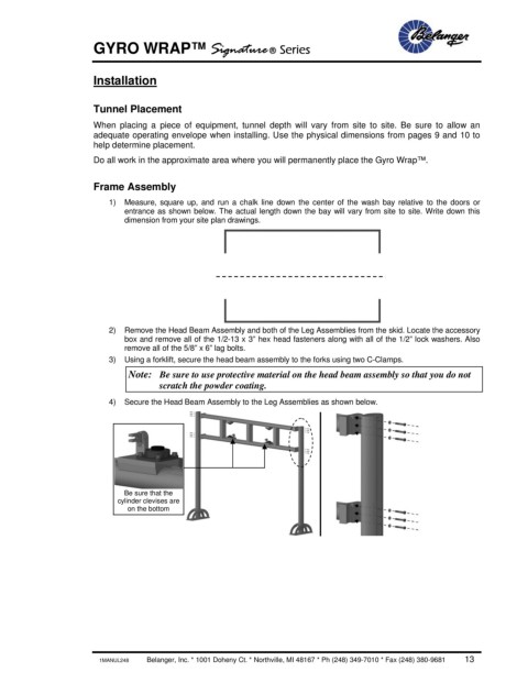
4) Secure the Head Beam Assembly to the Leg Assemblies as shown below.
Be sure that the
cylinder clevises are
on the bottom
1MANUL248 Belanger, Inc. * 1001 Doheny Ct. * Northville, MI 48167 * Ph (248) 349-7010 * Fax (248) 380-9681 13