
Page 35 - AirBlade® Dryer Signature® Series
P. 35
AIRBLADE® DRYER Signature ® Series
Installation
AirBlade® Select, Motor and Housing Installation with Side Kicks®
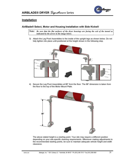
Note: Be sure that the flat surfaces of the dryer housings are facing the exit of the tunnel as
indicated by the arrow in the image below.
3) Attach the Leg Pivot Assemblies to the inside of the upright legs as shown below. Do not
fully tighten into place until positioned at the height shown in the following step.
4) Secure the Leg Pivot Assemblies at 88” from the floor. The 88” dimension is taken from
the floor to the top of the Motor Mount Plate.
88”
The above stated height is a starting point. Your site may require a different position
depending on your site-specific cleaning requirements. Whenever making adjustments to
the recommended starting points, be sure to maintain adequate vehicle height and width
clearance.
1MANUL009 Belanger, Inc. * 1001 Doheny Ct. * Northville, MI 48167 * Ph (810) 349-7010 * Fax (810) 380-9681 31