
Page 1623 - Foton Workshop Manual - Auman EST-M
P. 1623
Electrical system –circuit EL - 199
System description: IN
When the ignition switch is at ON/ST position, the currents flows through the pin 2 of the ignition switch to
the pin 85 of the IG1 relay R10 and the pin 86 is earthed. The coil is powered up to generate magnetic field. DI
Put the transmission gear into reverse position, the reversing lamp switch is closed, and makes the contacts of
the IG1 relay R10 closed. The current flows through the fuse 11 in the instrument panel fuse box and the fuse
EG
F05 in the vehicle frame fuse box to the pin 1 of the reversing lamp switch J003. Then the current is output
from the pin 2 of the reversing lamp switch to the pin 5 of the left rear combination lamp H012 and to the pin
5 of the left rear combination lamp H011 individually. The currents flow through the filaments of the TR
reversing lamps and the pin 1 of the left rear combination lamp1 and the pin 1 of the right rear combination
lamp are earthed. Both reversing lamps are on.
AX
Maintenance Precautions
● J003 reversing lamp switch
FR
1 - 2: activated when the transmission gear is put at reverse position.
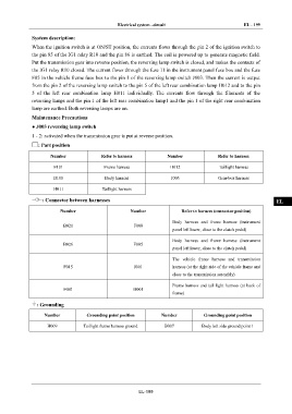
: Part position ST
Number Refer to harness Number Refer to harness
BR
F101 Frame harness H012 Taillight harness
B100 Body harness J003 Gear-box harness
BW
H011 Taillight harness
: Connector between harnesses EL
Number Number Refer to harness (connector position)
Body harness and frame harness (instrument
B021 F008
panel left lower, close to the clutch pedal)
Body harness and frame harness (instrument
B026 F005
panel left lower, close to the clutch pedal)
The vehicle frame harness and transmission
F015 J001 harness (at the right side of the vehicle frame and
close to the transmission assembly)
Frame harness and tail light harness (at back of
F041 H001
frame)
: Grounding
Number Grounding point position Number Grounding point position
H009 Taillight frame harness ground B007 Body left side ground point 1
EL-199