
Page 171 - Zoo Animal Learning and Training
P. 171
174 Section III: Spinal Procedures
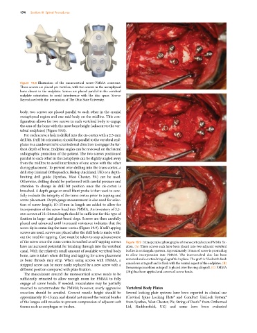
Figure 19.8 Illustration of the monocortical screw–PMMA construct.
Three screws are placed per vertebra, with two screws in the metaphyseal
bone closest to the endplates. Screws are placed parallel to the vertebral
endplate orientation to avoid interference with the disc space. Source:
Reproduced with the permission of The Ohio State University.
body, two screws are placed parallel to each other in the cranial
metaphyseal region and one mid‐body on the midline. This con-
figuration allows for two screws in each vertebral body to engage
the area of the bone with the most bone height (adjacent to the ver-
tebral endplates) (Figure 19.8).
For each screw, a hole is drilled into the cis‐cortex with a 2.5‐mm
drill bit. Drill bit orientation should be parallel to the vertebral end-
plates in a caudoventral to craniodorsal direction to engage the fur-
thest depth of bone. Endplate angles can be reviewed on the lateral
radiographic projection of the patient. The two screws positioned
parallel to each other in the metaphysis can be slightly angled away
from the midline to avoid interference of one screw with the other
during placement. To prevent over‐drilling into the trans‐cortex, a
drill stop (Animal Orthopaedics, Bishop Auckland, UK) or a depth‐
limiting drill guide (Synthes, West Chester, PA) can be used.
Otherwise, drilling should be performed with careful pressure and
attention to change in drill bit position once the cis‐cortex is
breached. A depth gauge or small blunt probe is then used to care-
fully evaluate the integrity of the trans‐cortex prior to tapping and
screw placement. Depth gauge measurement is also used for selec-
tion of screw length; 10–15 mm in length are added to allow for
incorporation of the screw head into PMMA. An inventory of 3.5‐
mm screws of 18–24 mm length should be sufficient for this type of
fixation in large‐ and giant‐breed dogs. Screws are then carefully
placed and advanced until increased resistance indicates that the
screw tip is contacting the trans‐cortex (Figure 19.9). If self‐tapping
screws are used, screws are placed after the drill hole is made with-
out the need for tapping. Care must be taken to stop advancement
of the screw once the trans‐cortex is reached as self‐tapping screws Figure 19.9 Intraoperative photographs of monocortical screw/PMMA fix-
have an increased potential for breaking through into the vertebral ation. (A) Three screws each have been placed into two adjacent vertebral
canal. With the relatively small amount of available vertebral body bodies in a triangular pattern. Approximately 10 mm of screw is protruding
bone, care is taken when drilling and tapping for screw placement to allow incorporation into PMMA. The intervertebral disc has been
as bone threads may strip. When using screws with PMMA, a removed and a cortical ring allograft is in place. The graft is filled with fresh
stripped screw can be more easily replaced by a new screw with a cancellous autograft and is flush with the ventral aspect of the endplates. (B)
different position compared with plate fixation. Remaining cancellous autograft is placed over the ring allograft. (C) PMMA
The musculature around the monocortical screws needs to be (20 g) has been applied and covers all screw heads.
sufficiently retracted to allow enough room for PMMA to fully
engage all screw heads. If needed, musculature may be partially
resected to accommodate the PMMA; however, overly aggressive Vertebral Body Plates
resection should be avoided. Cement mantle height should be Several locking plate systems have been reported in clinical use
approximately 10–15 mm and should not exceed the ventral border (Cervical Spine Locking Plate® and ComPact UniLock System®
of the longus colli muscles to prevent compression of adjacent soft from Synthes, West Chester, PA; String of Pearls™ from Orthomed
tissues such as esophagus or trachea. Ltd, Huddersfield, UK) and some have been evaluated