
Page 172 - Zoo Animal Learning and Training
P. 172
Chapter 19: Cervical Distraction and Stabilization 175
space. Monocortical drilling and careful tapping (unless self‐tap-
ping screws are used) commences as with regular screw placement.
Measurement for screw length is performed prior to tapping and
must be done through the locking plate, keeping in mind that
many of these plates will sit proud on the bone and screws will
traverse open space before engaging bone. The plate should be
held as close to the bone with digital pressure while maintaining it
in the desired position during screw application. Accurate place-
ment of the first screw is paramount, as this single screw, once
locked, will determine the path for all subsequent screws.
Other Techniques
As an alternative or augmentation to monocortical screw/PMMA
fixation of the vertebral bodies, bicortical screws can be placed in
the prominent transverse processes of the cervical vertebral column
(Figure 19.11). For medium to large dogs, 3.5‐mm cortical screws
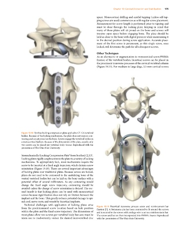
Figure 19.10 Synthes locking compression plate applied to C5–C6 vertebral
bodies. Because of the locking mechanism, the plate does not require con-
touring and can sit proud on the bone. Screws engage the vertebral bodies in
a monocortical fashion. Because of the dimensions of the plate, usually only
two screws can be placed per vertebral body. Source: Reproduced with the
permission of The Ohio State University.
biomechanically (Locking Compression Plate® from Synthes) [2,3,5].
Locking plates rigidly couple screws to the plate via a variety of locking
mechanisms. To appropriately lock, most mechanisms require the
screw to be inserted at a fixed angle trajectory, which dictates screw
orientation (Figure 19.10). There are several important advantages
of locking plates over traditional plates. Because screws are locked,
plates do not need to be contoured to the undulating bone of the
ventral vertebral bodies but can be laid on the bony surface with a
potential offset of several millimeters. As any contouring would
change the fixed angle screw trajectory, contouring should be
avoided unless the change of screw orientation is desired. The sec-
ond benefit is that locking plates can be used with monocortical
screws because rigid fixation does not rely on friction between the
implant and the bone. This greatly reduces potential damage to spi-
nal cord, nerve roots, and vessels by bicortical implants.
Technical challenges with application of locking plates arise
from the predetermined screw location based on hole position Figure 19.11 Bicortical transverse process screw and reinforcement bar
fixation [7]. A Steinmann pin has been contoured to fit around the screws
within the plate and the fixed screw trajectory. The dimensions of and is secured to the screws with cerclage wire to act as a reinforcement bar.
most plates allow two screws per vertebral body but care must be The screws and bar are then incorporated into PMMA. Source: Reproduced
taken not to inadvertently violate the slanted intervertebral disc with the permission of The Ohio State University.