
Page 173 - Zoo Animal Learning and Training
P. 173
176 Section III: Spinal Procedures
A B
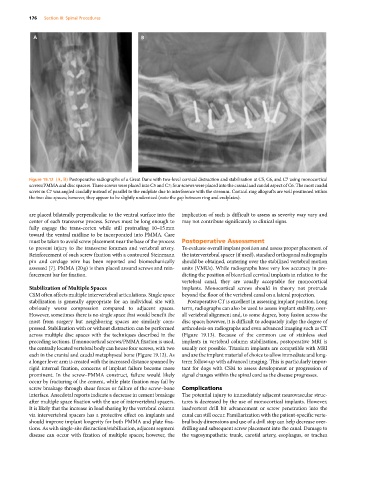
Figure 19.12 (A, B) Postoperative radiographs of a Great Dane with two‐level cervical distraction and stabilization at C5, C6, and C7 using monocortical
screws/PMMA and disc spacers. Three screws were placed into C5 and C7; four screws were placed into the cranial and caudal aspect of C6. The most caudal
screw in C7 was angled caudally instead of parallel to the endplate due to interference with the sternum. Cortical ring allografts are well positioned within
the two disc spaces; however, they appear to be slightly undersized (note the gap between ring and endplates).
are placed bilaterally perpendicular to the ventral surface into the implication of such is difficult to assess as severity may vary and
center of each transverse process. Screws must be long enough to may not contribute significantly to clinical signs.
fully engage the trans‐cortex while still protruding 10–15 mm
toward the ventral midline to be incorporated into PMMA. Care
must be taken to avoid screw placement near the base of the process Postoperative Assessment
to prevent injury to the transverse foramen and vertebral artery. To evaluate overall implant position and assess proper placement of
Reinforcement of such screw fixation with a contoured Steinmann the intervertebral spacer (if used), standard orthogonal radiographs
pin and cerclage wire has been reported and biomechanically should be obtained, centering over the stabilized vertebral motion
assessed [7]. PMMA (20 g) is then placed around screws and rein- units (VMUs). While radiographs have very low accuracy in pre-
forcement bar for fixation. dicting the position of bicortical cervical implants in relation to the
vertebral canal, they are usually acceptable for monocortical
Stabilization of Multiple Spaces implants. Monocortical screws should in theory not protrude
CSM often affects multiple intervertebral articulations. Single space beyond the floor of the vertebral canal on a lateral projection.
stabilization is generally appropriate for an individual site with Postoperative CT is excellent in assessing implant position. Long
obviously worse compression compared to adjacent spaces. term, radiographs can also be used to assess implant stability, over-
However, sometimes there is no single space that would benefit the all vertebral alignment and, to some degree, bony fusion across the
most from surgery but neighboring spaces are similarly com- disc space; however, it is difficult to adequately judge the degree of
pressed. Stabilization with or without distraction can be performed arthrodesis on radiographs and even advanced imaging such as CT
across multiple disc spaces with the techniques described in the (Figure 19.13). Because of the common use of stainless steel
preceding sections. If monocortical screws/PMMA fixation is used, implants in vertebral column stabilization, postoperative MRI is
the centrally located vertebral body can house four screws, with two usually not possible. Titanium implants are compatible with MRI
each in the cranial and caudal metaphyseal bone (Figure 19.12). As and are the implant material of choice to allow immediate and long‐
a longer lever arm is created with the increased distance spanned by term follow‐up with advanced imaging. This is particularly impor-
rigid internal fixation, concerns of implant failure become more tant for dogs with CSM to assess development or progression of
prominent. In the screw–PMMA construct, failure would likely signal changes within the spinal cord as the disease progresses.
occur by fracturing of the cement, while plate fixation may fail by
screw breakage through shear forces or failure of the screw–bone Complications
interface. Anecdotal reports indicate a decrease in cement breakage The potential injury to immediately adjacent neurovascular struc-
after multiple space fixation with the use of intervertebral spacers. tures is decreased by the use of monocortical implants. However,
It is likely that the increase in load sharing by the vertebral column inadvertent drill bit advancement or screw penetration into the
via intervertebral spacers has a protective effect on implants and canal can still occur. Familiarization with the patient‐specific verte-
should improve implant longevity for both PMMA and plate fixa- bral body dimensions and use of a drill stop can help decrease over‐
tions. As with single‐site distraction/stabilization, adjacent segment drilling and subsequent screw placement into the canal. Damage to
disease can occur with fixation of multiple spaces; however, the the vagosympathetic trunk, carotid artery, esophagus, or trachea