
Page 1323 - Workshop Manual - Aumark (BJ1051)
P. 1323
61-51
Circuit-System circuit diagram
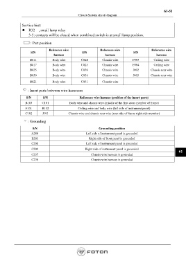
Service hint:
z R32 , small lamp relay
3-5: contacts will be closed when combined switch is at small lamp position.
: Part position
Reference wire Reference wire Reference wire
S/N S/N S/N
harness harness harness
B011 Body wire C024 Chassis wire F003 Ceiling wire
B017 Body wire C025 Chassis wire F004 Ceiling wire
B025 Body wire C030 Chassis wire J002 Chassis rear wire
B050 Body wire C036 Chassis wire J005 Chassis rear wire
B021 Body wire C051 Chassis wire
: Insert parts between wire harnesses
S/N S/N Reference wire harness (position of the insert parts)
B103 C101 Body wire and chassis wire (middle of the first cross member of frame)
F101 B112 Ceiling wire and body wire (left side of instrument panel)
C102 J101 Chassis wire and chassis rear wire (rear side of frame right side member)
: Grounding
S/N Grounding position
A204 Left side of instrument panel is grounded
B205 Right side of front panel is grounded
C208 Left side of instrument panel is grounded
C209 Right side of instrument panel is grounded
61
C237 Chassis wire harness is grounded
C238 Chassis wire harness is grounded
Page 1323