
Page 542 - Workshop Manual - Aumark (BJ1051)
P. 542
04-398
Diagnosis- Central Lock
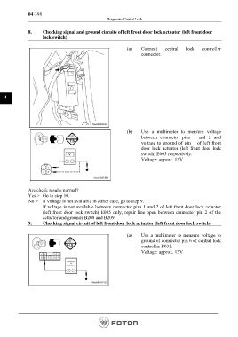
8. Checking signal and ground circuits of left front door lock actuator (left front door
lock switch)
(a) Connect central lock controller
connector.
4
(b) Use a multimeter to measure voltage
between connector pins 1 and 2 and
voltage to ground of pin 1 of left front
door lock actuator (left front door lock
switch) E005 respectively.
Voltage: approx. 12V
Are check results normal?
Yes > Go to step 10.
No > If voltage is not available in either case, go to step 9.
If voltage is not available between connector pins 1 and 2 of left front door lock actuator
(left front door lock switch) E005 only, repair line open between connector pin 2 of the
actuator and grounds B208 and B209.
9. Checking signal circuit of left front door lock actuator (left front door lock switch)
(a) Use a multimeter to measure voltage to
ground of connector pin 6 of central lock
controller B035.
Voltage: approx. 12V
Page 542