Page 789 - Workshop Manual - Aumark (BJ1051)
P. 789
26-33
                                                     Rear axle- rear wheel brake

               Front wheel brake


               Adjustment

               1.   Partial adjustment
               (a).  Clean the dirt and oil stains on the worm shaft head of the adjusting arm, set the wrench on the
                    hexagonal head and press down the lock sleeve to keep the worm shaft in non-locking state. (If
                    the lock sleeve can not be pressed down, a  hammer can be used to knock on the wrench
                    gently.)
               (b).  Rotate the worm shaft to make the clearance between the brake shoe and the brake drum
                    disappear, reverse the worm shaft for 1/2 ~ 2/3 revolution (normally 3-5 sounds) to make the
                    clearance between the brake shoe and the brake drum reach the required clearance. Do not
                    loosen the lock nut of the brake shoe pin or change the installation position of the camshaft to
                    avoid breaking the correct cooperation relationship between the brake shoe and the brake
                    drum.
               (c).  Rotate the brake drum after adjusting the brake clearance, if there is slight grating, enlarge the
                    clearance slightly. The deviation occurs during the driving is the inconformity of the left and
                    right brake clearance, which can be excluded by adjusting the clearance between the brake
                    shoe and the brake drum.

               2.   Complete adjustment
               (a).  prop the vehicle up and make the wheels leave the ground.
               (b).  Loosen the push rod clevis cotter pin of the brake chamber and remove the pin axle.
               (c).  Rotate the worm shaft to make the two brake shoes attach to the brake drum and the wheels
                    can’t move.
               (d).  Reverse the worm shaft for 1/2~2/3 revolution (normally 3-5 sounds) to make the brake drum
                    rotate freely without friction with brake shoe lining or other parts.
               (e).  Check the brake clearance and the clearance between the brake shoe lining and the brake drum.
               (f).  Adjust the brake chamber push rod stroke: Connect the brake chamber push rod clevis pin axle
                    and lock up the cotter pin. Loosen the push rod clevis lock nut and adjust the push rod stroke ,
                    the ideal brake chamber push rod stroke.                                                        26
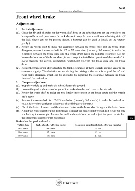
               Brake chamber push rod stroke.
                Vehicle type    Brake chamber effective stroke     Maximum adjustment stroke of brake chamber
                 1051 series              44.5 mm                                    35 mm
                 1061 series              57.1 mm                                    45 mm
                 1089 series              63.5 mm                                    51 mm


                                                                                                         Page 789

