
Page 138 - Fiber Optic Communications Fund
P. 138
Lasers 119
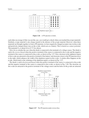
p-type n-type
− − + +
− − + +
− − + +
− − + +
Depletion region
Figure 3.26 A PN junction or diode.
each other on average (if this was not the case, you would get a shock when you touched the p-type material).
Similarly, n-type material is also charge neutral in the absence of the p-type material. However, when these
materials are brought together to form a PN junction, we have negatively charged acceptor ions on the p-side
and positively charged donor ions on the n-side, which acts as a battery. This is known as contact potential.
This potential V is about 0.6 to 0.7 V for silicon.
0
Next, let us consider the case when the diode is connected to the terminals of a voltage source. The diode is
said to be reverse-biased when the positive terminal of the source is connected to the n-side and the negative
terminal of the source is connected to the p-side, as shown in Fig. 3.27. Now, electrons in the rightmost region
of the n-side are attracted to the positive terminal of the battery, and electrons closer to the PN junction move
to the right, which enhances the width of the depletion region on the n-side. A similar effect happens on the
p-side, which leads to the widening of the depletion region, as shown in Fig. 3.27.
The diode is said to be forward-biased when the positive terminal of the source is connected to the p-side
and the negative terminal of the source is connected to the n-side, as shown in Fig. 3.28. The electrons on
the n-side are attracted to the positive terminal of the voltage source and the holes on the p-side are attracted
Depletion region before
reverse-bias
p-type n-type
* * * + + +
* * * + + +
* * * + + +
* * * + + +
Depletion region after
reverse-bias
* +
Figure 3.27 The PN junction under reverse-bias.