
Page 31 - DuraBlaster® Wheel Cleaner
P. 31
®
DURABLASTER WHEEL CLEANER
Installation
Pneumatic Startup (Rotating DuraBlaster® ONLY)
Start up the conveyor and force all dollies up. The ideal situation is to have one person ready to
adjust the tracking speed flow control on the driver side of the DuraBlaster® and a second person to
activate the tracking output on your controller. Alternatively, the following methods are also
acceptable: push the manual override button on the air solenoid on the air panel, step on the bell hose
or break the photo-eye. When a dollie is close to the location the DuraBlaster® is pointed, then
activate the tracking solenoid and watch to verify that the DuraBlaster® rotates toward the exit of the
tunnel while pointing at the dollie. If the DuraBlaster® rotates too fast, turn the flow control clockwise
(in), to slow it down. Turn the flow control counterclockwise (out) to speed it up. Repeat this
procedure until it follows the dollie closely. Next adjust the passenger side flow control to rotate at the
same speed as the driver side.
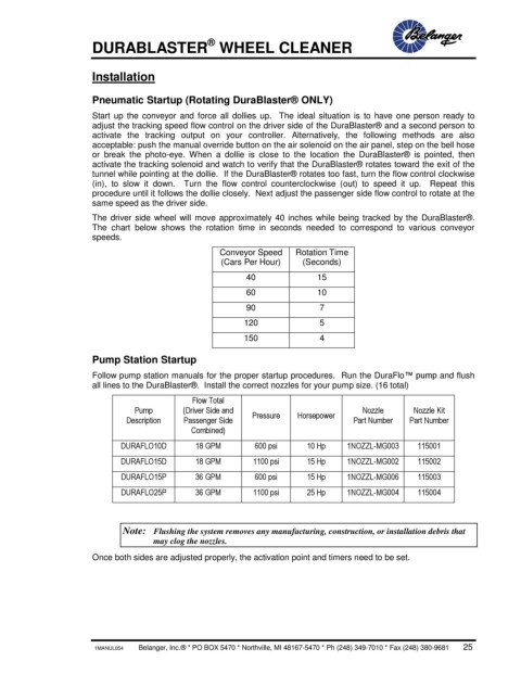
The driver side wheel will move approximately 40 inches while being tracked by the DuraBlaster®.
The chart below shows the rotation time in seconds needed to correspond to various conveyor
speeds.
Conveyor Speed Rotation Time
(Cars Per Hour) (Seconds)
40 15
60 10
90 7
120 5
150 4
Pump Station Startup
Follow pump station manuals for the proper startup procedures. Run the DuraFlo™ pump and flush
all lines to the DuraBlaster®. Install the correct nozzles for your pump size. (16 total)
Flow Total
Pump (Driver Side and Nozzle Nozzle Kit
Description Passenger Side Pressure Horsepower Part Number Part Number
Combined)
DURAFLO10D 18 GPM 600 psi 10 Hp 1NOZZL-MG003 115001
DURAFLO15D 18 GPM 1100 psi 15 Hp 1NOZZL-MG002 115002
DURAFLO15P 36 GPM 600 psi 15 Hp 1NOZZL-MG006 115003
DURAFLO25P 36 GPM 1100 psi 25 Hp 1NOZZL-MG004 115004
Note: Flushing the system removes any manufacturing, construction, or installation debris that
may clog the nozzles.
Once both sides are adjusted properly, the activation point and timers need to be set.
1MANUL054 Belanger, Inc.® * PO BOX 5470 * Northville, MI 48167-5470 * Ph (248) 349-7010 * Fax (248) 380-9681 25