
Page 967 - Foton Workshop Manual - Auman EST-M
P. 967
Axles, Transmission Shafts - Rear Axle AX-55
Check and adjust IN
1. Visually inspect the rear axle final reducer assembly
a. Check the driven gear for obvious stains, peeling, DI
defects and other abnormal phenomena and, if any,
replace the damaged parts.
Caution EG
If the driving gear is damage, replace the driven gear
at the same time as far as possible, for easy TR
adjustment of the gear backlash.
b. Check the differential bearing cover, the differential
case for cracks and other phenomena, and if necessary, AX
replace the damaged parts.
c. Check the final reducer housing for cracks and other
FR
phenomena, and if necessary, replace the parts.
2. Adjustment of the backlash of the planet gear and the axle shaft gear of transmission
a. When installing planetary gear, axle shaft gear and differential, adjust the thickness of the thrust washer of ST
axle shaft gear and adjust the axial thrust clearance of axle shaft gear to 0.25 ~ 0.4mm, and the rotation of
each gear by hand should be flexible without any jamming.
3. Adjustment of preload of driving gear bearings BR
a. After the installation of driving gear and the main reducer housing, adjust the shims thickness between the
front bearing and the spacer on the driving gear without oil seal. The preload of bearing measured at flange BW
should be between 0.25 ~ 0.4mm, and the rotation of the gear should be flexible without any delay.
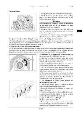
4. Adjustment of the backlash of the driving and the
driven gear and the total load of bearing. EL
a. Attach the magnetic dial indicator to the final reducer
housing with the contact rod perpendicular to the convex
surface of the big gear of the driven gear.
b. Turn the driven gear in one direction with hands to
contact with the driving gear, to zero set the gauge.
c. Turn the driven gear in the other direction to make
contact with the driving gear and read the value on the
dial indicator as the meshing clearance.
d. The measurement should be performed on at least
three teeth evenly distributed on the circumference, and
measured the meshing clearance and the difference of
clearance should meet the requirements.
5. The adjustment of contact prints between the
driving and the driven gear
a. Using red lead powder, apply 3 ~ 4 teeth on the passive
gear at three different positions respectively.
b. Rotate the driven gear several times in positive and
negative directions.
c. Check the meshing mark of the driving and the driven gears.
Location:Located in the middle of the driven gear
tooth surface and biased to the small end.
Length:≥ 60% of the tooth length
Width:≥ 60% of tooth width
If the meshing mark of driving and the driven gear is not
correct, then replace the adjustment shims of differential
bearing and the adjustment shims of driving gear.
AX-055