
Page 28 - GuardII+ Series 4208 Platform User Manual
P. 28
Installation
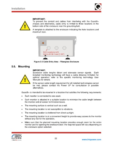
IMPORTANT:
To prevent the conduit and cables from interfering with the GuardII+
chassis and electronics, cable entry is limited to three locations in the
bottom side of the enclosure near the grounding bolt.
A template is attached to the enclosure indicating the hole locations and
maximum size.
Figure 5-3 Cable Entry Area – Fiberglass Enclosure
5.6. Mounting
IMPORTANT:
Excessive cable lengths distort and attenuate sensor signals. Each
installed monitoring technology will have a cable distance limitation for
optimal operation; refer to the specific monitoring technology User
Manuals for details.
If the sensor cable length requirement for all installed technologies cannot
be met, please contact Iris Power LP for consultation or possible
alternatives.
GuardII+ is intended to be mounted in a location that satisfies the following requirements:
• Each monitor is connected to one asset.
• Each monitor is situated in a suitable location to minimize the cable length between
the monitor and all sensor termination boxes.
• The mounting surface is vertical such as a wall.
• The mounting location is not susceptible to vibrations.
• The mounting location is sheltered from direct sunlight.
• The mounting location is at a convenient height to provide easy access to the monitor
without any risk for the operators.
• Make sure that the planned mounting location provides enough room for the entire
monitor and for opening the enclosure door; the required space will vary depending on
the enclosure option selected.
22
www.irispower.com