Page 783 - Workshop Manual - Aumark (BJ1051)
P. 783
26-27
                                                     Rear axle- rear wheel brake


               Front brake chamber


               Adjustment


               1.   Determine the initial length of the push rod during the installation of the brake chamber,
                    the horizontal angel between the adjusting arm and the chamber push rod can not exceed
                    100 °-105 °, otherwise, the initial force of the brake chamber will decline.
               2.   Fill 0.6 mpa compressed air into the diaphragm of the brake chamber and measure the
                    push rod route with a height gauge.
               3.   The adjustment for the stroke of brake chamber can not exceed the values in the table
                    below, otherwise, effective brake can not be guaranteed.

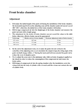
                    Vehicle tape      Effective stroke of brake chamber   Maximum adjustment stroke of brake chamber
                     1051 series                 44.5 mm                                35 mm
                     1061 series                 57.1 mm                                45 mm
                     1089 series                 63.5 mm                                51 mm

               4.   By the end of the adjustment route, try to make the push rod axis vertical to the
                    centerline of the adjusting arm so as to maximize the output torque.the swing angle of the
                    push rod shall change within ± 3 °during the back-and forth movementof the push rod to
                    reduce the wear of chamber parts.
               5.   Try to adjust the arm route to the minimum value while no brake dragging is applied on
                    the wheels in order to reduce the comsumption of the compressed air and ensure the
                    brake safety.
               6.   Fill 0.6mpa of compressed air into the spring chamber after the installation; screw the
                    release bolt into the body of cylinder with a wrench until the release nut contacts the nut
                    of cylinder body.
                                                                                                                    26


                                                                                                         Page 783

